if you want to copy, share, use etc. etc. all or part of this article you CAN DO IT, BUT please cite me and share the link to this article.
I'm not taking any responsibility for any kind of damage to your mouse, your PIC or yourselves XD
and yes, I posted this article on grix.com too (written in Italian).
OK, LET'S GO! :)
I needed a cheap (and accurate) motion sensor... What could be better than an optical mouse for the job? BUT... my PIC doesn't have a usb controller (and I'm cheap, so I don't want to buy a new one :p ) so I had to do things my way... :)
let's start with... “an optical mouse, how does it work????”
finding a useful mouse could be a bit hard: I've spent weeks trying to open up all the mice I could find (kindly offered by friends, parents etc. etc.), so I learnt what kind of chips you can get from a usb optical mouse:
the “made in china” mice contain chips that use the computer for motion processing... that kind of mouse doesn't work well with my code, but you can find a good mouse in second-hand shops or places like that.
The mice I've tried, with good results, are based on ADNS2051 and ADNS2610 chips.
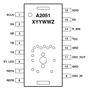
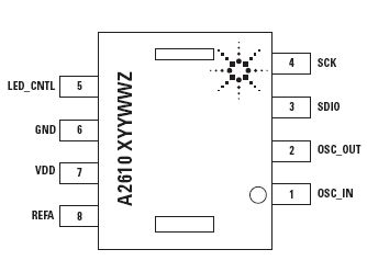
I think that there are probably other mice using the same protocol (or quite similar), but I only tried with those two chips. For the purposes of this article, I shall illustrate how to use the ADNS2610 chip.
these chips are EXTREMELY sensitive to the polarity inversion: I broke a mouse just because I messed up with the polarity, so CHECK THE DATASHEET BEFORE YOU START! And check and re-check all the wires!
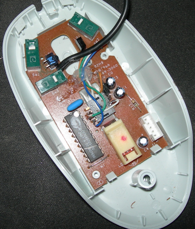
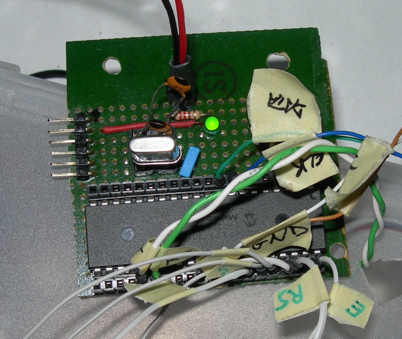
You can supply the chips with VDD – GND pins by soldering the wires directly on to the pins: in that way you can easily re-convert the sensor to a “common mouse” because this is the only modification that you have to make to the mouse itself.
The protocol used for the mouse-pc communication is a serial, bi-directional, half-duplex clock driven (the clock is generated by the PIC and shared both by the mouse and the PIC). Then, for the connection, you can use two wires: SCK pin (the clock) and SDIO pin (data line). So you have to solder just 4 wires in total: 2 for supply and 2 for communication.
This is a picture of the mouse that I used, after the mod:
how it works: theory of operation
After the connection phase, let's see how the mouse works.
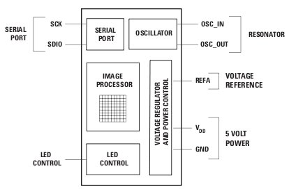
An optical mouse is based on “Optical Navigation Technology”: it contains an Image Acquisition System (IAS) and a Digital Signal Processor (DSP).
A mouse reads any motion by acquiring sequential images by IAS module and mathematically confronting these images to determin the displacement (by DSP module).
In the next image you can see the logical architecture, where DSP and IAS are both integrated in the "IMAGE PROCESSOR".
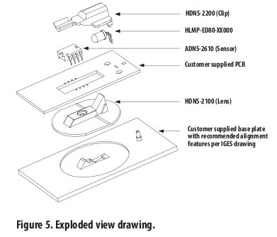
The next diagram is of the inside of the mouse:
The displacement data is automatically stored in the registers of the chip... but how can we retrieve this data?
Communication protocol
The protocol used by ADNS2051 is harder to understand than the one used by ADNS2610 this is because it requires an initialization phase and a check on a state register before every reading.
The communication protocol is quite similar in every chip I've seen, so if you can understand the theory of operation you will be able to use any kind of mouse chip.
A serial communication is used for the read/write operations on the registers of the mouse chip and to read displacement informations (this is what we are interested in).
The communication is always initiated by the microcontroller.
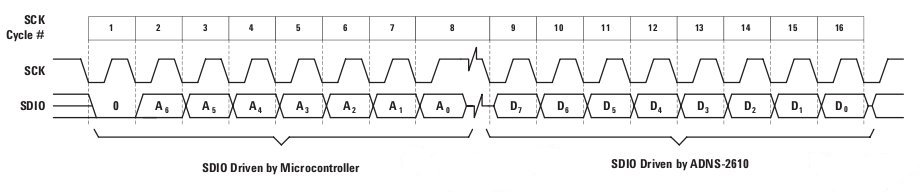
The maximum amount of displacement that a mouse can “feel” from reading to reading is formed by 7 bits (8 in total, but one of them is just for the sign) so 2^7=128.
The transfer is synchronized by SCK. SDIO is changed on falling edges of SCK and read on every rising edge of SCK. (look at the code below, it's simpler!). There are minimum timing requirements between read and write commands on the serial port: we have to ensure that the ADNS-2610 has at least 100 μs to prepare the requested data.
In the following image you can see the ADNS2610 registers:
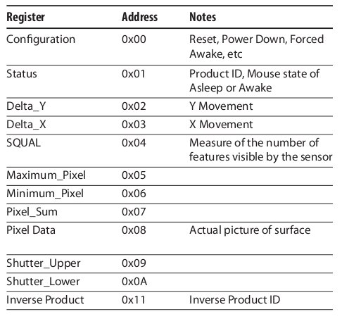
The 0x08 register is quite interesting and useful since you can read the pixel seen by the mouse sensor by means 324 consecutive reading according to the following table. (the return value will represents the pixel intensity)
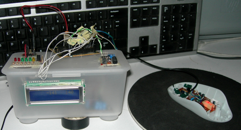
Practice – the circuit
The table basically shows a 16F877 PIC clocked at 4Mhz. I used the E-port for the mouse connection and the B-port for a 16x2 characters LCD (everything works fine at 5v).

the assembling phase:
Practice – the code
I wrote the code in MikroC language (you can find it attached at the end of this article).
This is the “hello world” of my project: in this way you can retrieve the coordinates and... do what you want to do with this data.
Let's start with the main(), which reads the value of the registers and writes it on the LCD (in a loop, after the port and LCD initialization).
The register contains a two's complement value, so you can simply add this value, which is only the displacement from the last reading phase, to the “global/final position”.
void main(){
init_LCD_PIC();
for(;;) {
x += readRegister(DX);
y += readRegister(DY);
LCDWriteResult(x,y);
}
}
init_LCD_PIC();
for(;;) {
x += readRegister(DX);
y += readRegister(DY);
LCDWriteResult(x,y);
}
}
This code reads from the register (THIS IS THE CORE OF THE PROJECT):
signed short readRegister(const register unsigned short int address){
signed short output = 0;
signed short i = 0;
//direction WRITING
DIRDATA = OUT;
//write address of register to be read
for(i=7;i!=-1;i--){
MOUSE_CLK = 0;
MOUSE_DATA = 1 && ((address & (1<<i))>0);
MOUSE_CLK = 1;
}
//direction READING
DIRDATA=IN;
//wait for data
Delay_us(100);
//read the data
for(i=8;i!=0;i--) {
MOUSE_CLK = 0;
MOUSE_CLK = 1;
output |= MOUSE_DATA << i-1;
}
return output;
}
explanation: DIRDATA is the read/write serial state.
The first for loop sends the first byte of data to the mouse, using the clock for the synchronization.
The second one “composes” the result bit by bit, reading the data that come from the mouse.
Comments? Any questions? Use the “Comments” button :)
THANKS TO TIZIANA (TES T) FOR HELPING ME WITH EVERY ITALIAN-ENGLISH TRANSLATION!
THANKS TO TIZIANA (TES T) FOR HELPING ME WITH EVERY ITALIAN-ENGLISH TRANSLATION!
HI SIR
RispondiEliminaI USED YOUR CODE FOR USB MOUSE, BUT I NEEDED OUTPUT THROUGH UART MODULE OF MY PIC MICRO CONTROLLER, SO I EDITED YOUR PROGRAM AND USED IT, I GOT OUTPUT, BUT THE OUTPUT IS NOT CONSTANT EVEN WHEN THE MOUSE IS NOT MOVING, PLEASE HELP ME, I DON'T KNOW WHAT IS WRONG, IF I DIDN'T GET THIS MY PROJECT WILL BE IN DANGER, PLEASE HELP PLEASE...
the value of x and y registers goes on incrementing, and i never get values as you obtained on lcd my maximum value is 255...
RispondiEliminathis is the code i used, please do help me....
#define DY 0x02
#define DX 0x03
#define IN 1
#define OUT 0
//MOUSE PORTE bit 0, 1
sbit DIRDATA at TRISE1_bit;
sbit MOUSE_DATA at RE1_bit;
sbit MOUSE_CLK at RE0_bit;
// LCD PORTB
/*sbit LCD_RS at RB5_bit;
sbit LCD_EN at RB6_bit;
sbit LCD_D4 at RB1_bit;
sbit LCD_D5 at RB2_bit;
sbit LCD_D6 at RB3_bit;
sbit LCD_D7 at RB4_bit;
sbit LCD_RS_Direction at TRISB5_bit;
sbit LCD_EN_Direction at TRISB6_bit;
sbit LCD_D4_Direction at TRISB1_bit;
sbit LCD_D5_Direction at TRISB2_bit;
sbit LCD_D6_Direction at TRISB3_bit;
sbit LCD_D7_Direction at TRISB4_bit;*/
signed short readRegister(const register unsigned short int address){
signed short output = 0;
signed short i = 0;
//direction WRITING
DIRDATA = OUT;
//write address of register to be read
for(i=7;i!=-1;i--){
MOUSE_CLK = 0;
MOUSE_DATA = 1 && ((address & (1<0);
MOUSE_CLK = 1;
}
//direction READING
DIRDATA=IN;
//wait for data
Delay_us(100);
//read the data
for(i=8;i!=0;i--) {
MOUSE_CLK = 0;
MOUSE_CLK = 1;
output |= MOUSE_DATA << i-1;
}
return output;
}
/*void LCDWriteResult(int x, int y){
char str[6];
memset(str,0,5);
intToStr(x, str);
Lcd_Out(1,4,str);
memset(str,0,5);
intToStr(y, str);
Lcd_Out(1,10,str);*/
}
void init() {
ADCON1=0x07;
TRISE=0;
PORTE=0;
UART1_Init(9600);
//Lcd_Init(); // Initialize LCD
// Lcd_Cmd(_LCD_CLEAR); // Clear display
// Lcd_Cmd(_LCD_CURSOR_OFF); // Cursor off
}
void main(){
long x = 0, y = 0;
unsigned short i=0;
init();
for(;;) {
x += readRegister(DX);
y += readRegister(DY);
UART1_Write(x);
UART1_Write(y);
//LCDWriteResult(x,y);
}
}
Trying to read the datasheet to see if you are reading the wrong register... what kind of mouse chip are you using?
RispondiEliminasame adns 2610, it is the same like the one you showed in this blog, i get output, but not correct values it is something that goes on counting from 0 to 255 then again starts....
RispondiEliminatry to put something like this in your main loop:
RispondiEliminafor(;;) {
UART1_Write(readRegister(DX));
UART1_Write(readRegister(DY));
}
what do you receive?
no i tried to directly write the value of the 'output' variable (which is same as your suggestion) but what i got was 0 and 255
RispondiEliminaI don't know, try to change the value for the registers
RispondiElimina#define DY 0x02
#define DX 0x03
try with some different values, you can find it in the datasheet (page 18).
and why do you used ADCON? you don't use PORTA???
RispondiEliminaplease help.
RispondiEliminaI am making this interface to 2610.
But when I plug the pic on the LCD I get a counter that does not stop.
What version of MikroC use?
And how to set the fuse bits.?
Thanks.
If you see a counter never stops, you're reading from the wrong register (maybe the "serial number id" one). Change the address you're reading from in according with your chip datasheet.
RispondiEliminaThis counter is even without connecting the A2610.
RispondiEliminaThe sensor I have is the A2610 C0312. That is written on the chip.
Sorry you broke the tracks that connect the mouse chip DSP.?
Ill use google translate to translate this for you
RispondiEliminaI wanted to make a program that read the amount of "dark" (or different pixels of some sort) pixels from the 18x18 camera, and once it reads this number it will display some other number that will appear on an 7-pin LCD Display
for example, say there are 159 "Different" pixels out of 324, it will display 15 on the screen, any idea how to do that?
Volevo fare un programma che legge la quantità di "nero" (o pixel differenti di qualche tipo) pixel dalla fotocamera 18x18, e una volta lo legge questo numero verrà visualizzato un altro numero che apparirà in un 7-pin Display LCD
per esempio, dire che ci sono 159 "diverso" su 324 pixel, visualizza 15 sullo schermo, qualsiasi idea di come farlo?
ZIPPED SOURCE FILE
RispondiEliminaFile does not exist
fixed ;) now on sourceforge...
RispondiEliminaHi
RispondiEliminathanks for your useful project...
but i have a problem , i can't download the attachment.
could you please mail me the source files ?
shahrokh_es65@yahoo.com
Regards, shahrokh
Hi
RispondiEliminathanks for your useful project...
but i have a problem , i can't download the attachment.
could you please mail me the source files ?
shahrokh_es65@yahoo.com
Regards, shahrokh
hello my counter keeps on increasing even without connecting sensor . can you tell me what is the problem in this.
RispondiEliminaThanks
someone already asked... i think you are reading the wrong register or some other problems in your code...
RispondiEliminahow to convert this program to 8051 assembly or c because i want to use 8051 micro controller any idea
RispondiEliminathe software IS in c (or almost c-like). it should be very easy to convert it if you have a c compiler for your processor.
RispondiEliminaHi, I have same problem like others, counter keeps increasing always. So, would you mind sharing your project file here? .c source file is already here but I mean total MikroC project file. Thanks for your helping...
RispondiElimina...and the answer is the same... you are probably reading from the wrong register. Too much time passed, i really don't know where i put the entire project, i'm sorry...
RispondiEliminais to send me the code?
RispondiEliminaroland.2008@hotmail.com
don't you like sourceforge? :)
RispondiEliminaIn datasheet the operating voltage is given as 3.3v max. But my microcontroller operates at 5V. Then how to interface mouse? My mouse IC name - ADNS-2080. Please suggest a solution.
RispondiEliminaif you use a PIC microcontroller, check the datasheet because maybe you could use 3,3v for it as well.
RispondiEliminado you want to power on the chip "alone"? otherwise you can supply 5v directly on the mouse cable (but i'm not sure if it'll work).
anyway, you should use a linear regulator to reduce to 3,3v from 5v (check for example the Texas Instruments' catalog) OR a simple LM317 regulated to output the voltage you wish.
if your 5v is already a regulated voltage, you can simply use a voltage divider (http://en.wikipedia.org/wiki/Voltage_divider) or a couple of 1N4007 diodes ( 5- 1,4=3,6V ).
this was for power supply... to adapt the logic levels you have to use a "level shifter" circuit, you can build one your own or buy it on internet for few bucks.
I am using atmega128. Have you connected the data and clk pins directly to microcontroller? I had tried but was not working.
RispondiEliminai don't know about the atmega, does it have 3v3 logic level? yes i connected the wire directly
RispondiEliminaQuesto commento è stato eliminato dall'autore.
RispondiEliminaQuesto commento è stato eliminato dall'autore.
RispondiEliminahi
RispondiEliminathank for your useful project,but i have a question . . .
how we can detect a right or left click?
I want to do something with right or left Click. . .
thanks
Hello,
RispondiEliminaHelp me , my computer dont display the value to the terminal
Program here: ( programed with CCS 4.1)
Thank you in advance :)
#include
#org 0x1F00, 0x1FFF void loader16F877(void) {}
#define DY 0x02
#define DX 0x03
//SET_TRIS_C(0x02) port RC1 en entrée (DIRDATA = IN)
//SET_TRIS_C(0x00) tous les ports C en sortie (DIRDATA = OUT)
signed int8 readRegister(unsigned int8 address)
{
signed int8 Byte_Recep = 0;
int8 i = 0;
int1 bit_address;
int1 bit_recep;
SET_TRIS_C(0x80); //tout en sortie CLK et DATA sauf RXD (RC7)
//adress
for(i=0;i<8;i++)
{
output_low(MOUSE_CLK);
bit_address=shift_left(&address,1,0);
output_bit(MOUSE_DATA, bit_address);
output_high(MOUSE_CLK);
}
//read data
SET_TRIS_C(0x82); //MOUSE_DATA en entrée
//wait for data
Delay_us(100);
for(i=0;i<8;i++)
{
output_low(MOUSE_CLK);
output_high(MOUSE_CLK);
bit_recep=input(MOUSE_DATA);
shift_left(&Byte_Recep,1, input(MOUSE_DATA));
}
return Byte_Recep;
}
void main(){
signed int16 x,y;
SET_TRIS_C(0x80); //tout en sortie CLK et DATA suf RXD (RC7)
output_c(0b01000000); // RC1 =RC2=0
x = 0;
y = 0;
while(1) {
x += readRegister(DX);
delay_ms(10);
y += readRegister(DY);
delay_ms(10);
printf("x= %Ld , y= %Ld\n\r",x,y);
}
}
i want to increase the mouse position...with A2633 chip can your program be used?
RispondiEliminamikymouse,por favor passa seu e-mail.
RispondiEliminaQuesto commento è stato eliminato dall'autore.
RispondiEliminaMale Maltipoo Puppy
RispondiEliminaBuy Maltipoo puppy in California Clyde is a very happy puppy. He adores his humans and loves cuddles. They are raised with lots of early socialization to ensure that they get the best head start on life that we can give them. His mom, Lulu, is a cream Maltipoo and is registered. Maltipoo puppy sale Clyde has a puppy wellness check from the vet. He will go home with a record.
https://maltipooparadisehome.com/maltipoo-dogs-for-sale/
https://maltipooparadisehome.com/toy-maltipoo-puppies-for-sale-maltipoo-grooming/
https://maltipooparadisehome.com/maltipoo-puppies-for-sale-in-california/
https://maltipooparadisehome.com/puppies-for-sale-philadelphia-buy-now/
https://maltipooparadisehome.com/maltipoo-puppies-availalble/
https://maltipooparadisehome.com/maltipoo-for-adoption/
https://maltipooparadisehome.com/black-maltipoo-puppies-buy-now/
https://maltipooparadisehome.com/puppies-for-sale-in-ny/
https://maltipooparadisehome.com/puppies-for-sale-in-texas-buy-now/
Contact here for MORE DETAIILS....
https://maltipooparadisehome.com/
Phone: +1 (816) 259-0491